File:Memoria elettromeccanica per il calcolatore IBM 602A - Museo scienza tecnologia Milano D1191.jpg

Original file (1,280 × 906 pixels, file size: 801 KB, MIME type: image/jpeg)
| This is a file from the Wikimedia Commons. The description on its description page there is shown below.
|
| memoria elettromeccanica per il calcolatore IBM 602A
( |
||||||||||||||||||||||||
|---|---|---|---|---|---|---|---|---|---|---|---|---|---|---|---|---|---|---|---|---|---|---|---|---|
| Author |
I.B.M. Italia (costruttore/ produttore/ progettista), Daly Geore F. (progettista) |
|||||||||||||||||||||||
| Title |
memoria elettromeccanica per il calcolatore IBM 602A |
|||||||||||||||||||||||
| Description |
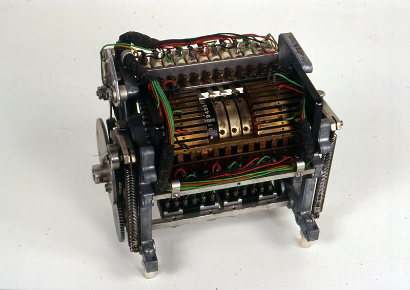
Italiano: Il dispositivo è montato su un telaio in alluminio pressofuso che presenta nella parte inferiore due blocchi di connettori divisi ciascuno in due gruppi da 12 e 6 "pin" (in totale 36 pin), sui lati una serie di ruotismi e molle e nella parte superiore vari dispositivi elettromeccanici. Dai due blocchi di connettori si dipartono 36 fili di rame rivestiti (18+18) che terminano ai dispositivi posti sul lato superiore del telaio: 14 fili vanno verso 13 relè, 12 verso pari contatti striscianti, 10 terminano su una serie di espansioni metalliche (10 sul lato destro e 10 su quello sinistro del dispositivo) collegandosi, in modo alterno sequenziale, a 5 espansioni sul lato destro e 5 sul lato sinistro (partendo da destra, la prima espansione in alto è collegata, la seconda no, fino ad arrivare all'ultima in alto a sinistra non collegata); tutte le espansioni sono munite di foro per la connessione di cavetti. La disposizione delle espansioni è simmetrica rispetto al telaio e le due serie, di destra e di sinistra, coprono ciascuna 4 semidischi in plastica per una metà ricoperti con una striscia metallica e l'altra metà dentata riportante 10 gradini disposti a dente di sega e numerati da 0 a 9. La parte dentata dei semidischi è rivolta verso l'ancorina di 12 dei 13 relè di cui sopra, mentre la parte ricoperta dalla lamina metallica è in connessione con i contatti striscianti. Altri 4 semidischi parimenti fatti sono posti centralmente e scoperti rispetto alle due serie di espansioni di cui sopra. Complessivamente i semidischi sono dodici e sono inseriti su un asse che ne comanda la rotazione di mezzo giro, per l'altro mezzo giro essi sono liberi di ruotare attorno all'asse stesso; la loro rotazione è regolata da molle in tensione. Con il meccanismo in funzione, 12 dei 13 relè trattengono con le estensioni delle proprie ancorine la rotazione dei semidischi, il tredicesimo, posto su di un lato del telaio, libera lo scatto di due molle poste una a destra e l'altra a sinistra esteriormente al telaio, che fanno ruotare di mezzo giro l'asse dei semidischi che così sono riportati in posizione di riposo Nella parte inferiore del telaio è installato un albero che sul lato del telaio del tredicesimo relè, all'esterno, presenta, solidali tra esse e calettate all'estremità dell'albero, una camma e una ruota dentata; quest'ultima è ingranata da un'altra ruota dentata posta inferiormente a guisa di terminale libero e avente l'asse di rotazione solidale al telaio. La rotazione della camma agisce sull'albero dei semidischi.
Questo dispositivo è una memoria di tipo elettromeccanica a dodici posizioni e due sezioni, che, sotto forma di posizione relativa di ruote di conteggio (semidischi numerati) memorizza dati numerici riportati da lettori di schede perforate sotto forma di segnali elettrici. Nel calcolatore IBM 602, esso rappresenta una delle sei unità che ne costituivano la memoria e la loro funzione era duplice: venivano utilizzati per immagazzinare i dati numerici riportati sulle schede perforate usate come memoria temporanea durante il calcolo e come output, alla fine di ogni fase di calcolo, per stampare i risultati.
L'utilizzo avveniva all'interno del calcolatore IBM 602A
|
|||||||||||||||||||||||
| Date | between 1948 and 1948 | |||||||||||||||||||||||
| Medium | acciaio | |||||||||||||||||||||||
| Dimensions | height: 18 cm (7 in); width: 12 cm (4.7 in) Weight: 28 kg (62.18 lb) | |||||||||||||||||||||||
| Collection |
|
|||||||||||||||||||||||
| Accession number |
D 1191 |
|||||||||||||||||||||||
| Object history | I.B.M. Italia | |||||||||||||||||||||||
| References |
|
|||||||||||||||||||||||
| Source/Photographer | Catalogo collezioni (in it). Museoscienza.org. Museo nazionale della scienza e della tecnologia Leonardo da Vinci, Milano. | |||||||||||||||||||||||
| Permission (Reusing this file) |
This file is licensed under the Creative Commons Attribution-Share Alike 4.0 International license.
|
|||||||||||||||||||||||

{{en 1=The device is mounted on a die-cast aluminum frame which has, in the lower part, two blocks of connectors, each divided into two groups of 12 and 6 "pins" (in total 36 pins), on the sides a series of gearings and springs and in the upper part various electromechanical devices. 36 coated copper wires branch off from the two blocks of connectors (18+18) which terminate at the devices located on the upper side of the frame: 14 wires go towards 13 relays, 12 towards equal sliding contacts, 10 terminate on a series of metal expansions ( 10 on the right side and 10 on the left side of the device) by connecting, alternately sequentially, to 5 expansions on the right side and 5 on the left side (starting from the right, the first expansion at the top is connected, the second is not, up to to the last top left not connected); all expansions have a hole for connecting cables. The arrangement of the expansions is symmetrical with respect to the frame and the two series, right and left, each cover 4 plastic half-discs, one half covered with a metal strip and the other toothed half bearing 10 steps arranged in a sawtooth pattern and numbered from 0 to 9. The toothed part of the half-discs faces the anchor of 12 of the 13 above relays, while the part covered by the metal foil is in connection with the sliding contacts. Other 4 similarly made half-discs are placed centrally and uncovered with respect to the two series of expansions mentioned above. Altogether there are twelve half-discs and they are inserted on an axis which controls their rotation of half a turn, for the other half turn they are free to rotate around the axis itself; their rotation is regulated by tensioned springs. With the mechanism in operation, 12 of the 13 relays hold the rotation of the half-discs with the extensions of their anchors, the thirteenth, placed on one side of the frame, releases the release of two springs placed one on the right and the other on the left externally to the frame, which rotate the axis of the half-discs by half a turn, which are thus brought back to the rest position. In the lower part of the frame, a shaft is installed which, on the side of the frame of the thirteenth relay, on the outside, presents, integral with keyed to the end of the shaft, a cam and a gear wheel; the latter is engaged by another toothed wheel located below as a free terminal and having the rotation axis integral with the frame. The rotation of the cam acts on the half-disc shaft.
Function
This device is a twelve-position, two-section electromechanical type memory, which, in the form of the relative position of count wheels (numbered halves) stores numerical data reported by punched card readers in the form of electrical signals. In the IBM 602 calculator, it represents one of the six units that made up the memory and their function was twofold: they were used to store the numerical data shown on the punched cards used as temporary memory during calculation and as output, at the end of each phase calculation, to print the results.
Method of use
They were used inside the IBM 602A calculator Historical-critical information The IBM 602, and therefore the subsequent IBM 602-A, were calculators capable of executing sequences of operations memorized in the form of a "program" (it is the term used by the IBM manuals relating to these machines), or, physically, stored on a "plugboard" (called control panel) equipped with hub matrices which, wired manually and inserted into a special connector of the computer (precisely in the rack of its Program Unit), complete some of its circuits.}}
File history
Click on a date/time to view the file as it appeared at that time.
| Date/Time | Dimensions | User | Comment | |
|---|---|---|---|---|
| current | 01:29, 21 May 2016 | 1,280 × 906 (801 KB) | Federico Leva (WMIT) | {{ICCD TRC | institution = {{institution:Museoscienza}} | permission = {{cc-by-sa-4.0}} | BIB3D = 1980 | RSR1 = Reduzzi, Luca | NSC = Le IBM 602, e quindi la successiva IBM 602-A, erano dei calcolatori capaci di eseguire sequenze di operazioni memor... |
File usage
The following page uses this file: