Electrical impedance
| Electromagnetism |
|---|
 |
| Electricity · Magnetism · Magnetic permeability |

Electrical impedance is the amount of opposition that a circuit presents to current or voltage change.
The two main ways to write an impedance are: (see the 2nd figure, "complex impedance plane")
- with the resistance "R" (real part) and the reactance "X" (imaginary part), for example [math]\displaystyle{ Z = 1 + 1j }[/math]
- with a magnitude and a phase (the size [math]\displaystyle{ \left\vert Z \right\vert }[/math] and the angle [math]\displaystyle{ \angle\theta }[/math]), for example [math]\displaystyle{ Z = 1.4 \angle 45^\circ }[/math] (1.4 ohm at 45 degrees)
The Impedance and the resistance are quite similar:
In the case of resistance, a resistor resists any current going through it. The higher the resistance, the higher the voltage that is needed to achieve a given current. The formula is:
[math]\displaystyle{ V = R * I }[/math], where V is the voltage, R is the resistance, and I is the current.
In the case of impedance, an inductor resists changes to the current and the capacitor resists changes to the voltage.
The key difference between resistance and impedance is the word "change", the rate of change affects the impedance. Usually the "change" is expressed as a frequency, the number of times per second the current or voltage change direction. The formulas are:
For the inductor: [math]\displaystyle{ Z=j 2 \pi f L \, }[/math]
For the capacitor: [math]\displaystyle{ Z=\frac{1}{j 2\pi f C} }[/math]
Where Z is the symbol for impedance, j is the imaginary number [math]\displaystyle{ \sqrt{-1} }[/math], [math]\displaystyle{ \pi }[/math] is the constant pi, f is the frequency, L is the inductance and C is the capacitance. The units for the resistance and the impedance are the same, the ohm with the symbol [math]\displaystyle{ \Omega }[/math] (capital omega).
As indicated by the formulas above, the impedance varies depending on the frequency, for example, at zero Hertz, or DC, the impedance of the inductor is zero, the same as a short-circuit, and the impedance of the capacitor is infinite, the same as an open-circuit. Most signals are the sum of many sine waves at various frequencies (see the fourier transform for more details), and each of them experience a different impedance.
Similarly to the resistance, the higher the impedance, the higher the voltage that is needed to achieve a given current. The formula is:
[math]\displaystyle{ V = Z * I }[/math], where V is the voltage, Z is the impedance, and I is the current.
At the physical level, simplifying many things:
- the resistance is caused by the collisions of the electrons with the atoms inside the resistors.
- the impedance in a capacitor is caused by the creation of an electric field.
- the impedance in an inductor is caused by the creation of a magnetic field.
One important difference between the resistance and the impedance is that a resistor dissipates energy, it gets hot, but an inductor and a capacitor store the energy and can return that energy to the source when it goes down.
If the impedance of the source, cable and load are not all equal, then a fraction of the signal is reflected back to the source, wasting power and creating interference. The ratio of the reflection can be calculated with:
- [math]\displaystyle{ \Gamma = {Z_L - Z_S\over Z_L + Z_S} }[/math] where [math]\displaystyle{ \Gamma }[/math] (capital gamma) is the Reflection coefficient, [math]\displaystyle{ Z_S }[/math] is the impedance of the source, [math]\displaystyle{ Z_L }[/math] is the impedance of the load.
Any medium that can have a wave has a wave impedance, even empty space (light is an electro-magnetic wave and it can travel in space) has an impedance of about 377[math]\displaystyle{ \Omega }[/math].
Phase

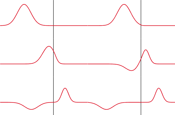
Across a resistor, both the voltage and the current goes up and down at the same time, they are said to be in phase, but with an impedance it's different, the voltage is shifted by 1/4 wavelength behind the current in a capacitor, and forward in an inductor.
A 1/4 wavelength is usually represented with the imaginary number "j", which is also equivalent to a 90 degree shift.
The use of the imaginary number "j" makes the mathematics much simpler, it allows to calculate the total impedance the same way as it's done with resistors, for example a resistor plus an impedance in series is R+Z, and in parallel it's (R*Z)/(R+Z).
Electrical Impedance Media
An AC supply applying a voltage V, across a load Z, driving a current I
A pack of resistors. Actual size
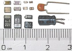
Capacitors: SMD ceramic at top left; SMD tantalum at bottom left; through-hole tantalum at top right; through-hole electrolytic at bottom right. Major scale divisions are cm. Actual size


